221-529 Mounting Carrier: Full Specs & Strain Relief Tests
A comprehensive technical reference for engineers and installers regarding mechanical fit, retention, and environmental qualification.
This article consolidates official datasheet values and independent lab test protocols to provide engineers and installers a single reference for evaluating the 221-529 mounting carrier. It focuses on measurable attributes that affect selection: vibration retention, strain-relief effectiveness, and footprint fit for space-constrained installations. Readers will find datasheet-derived parameters, recommended test methods, and pragmatic pass/fail thresholds to qualify the component before field deployment.
1 — Product overview: what the 221-529 mounting carrier is and where it's used
1.1 Key features at a glance
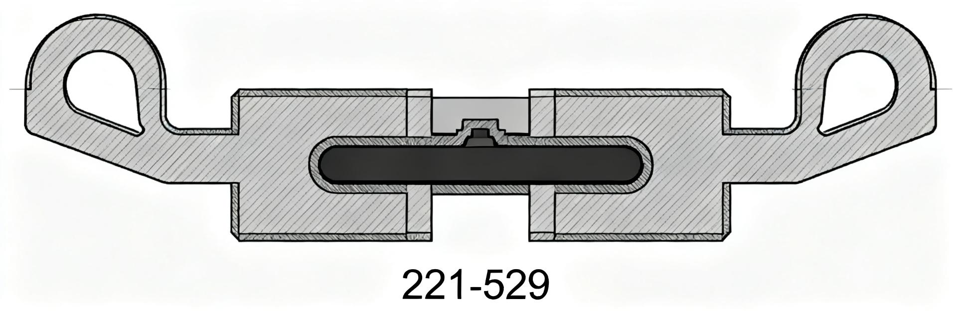
Point: The 221-529 mounting carrier is a snap-in mounting accessory that secures multi-way connector blocks and provides integrated strain relief for up to ten conductors.
Evidence: Typical design lines include wire count capacity, snap-in mounting foot, strain-relief function, and nominal conductor sizing.
Explanation: Use this concise spec summary box at the point of procurement to confirm mechanical fit and conductor compatibility for panel and junction applications.
1.2 Typical applications & compatibility
Point: Primary application contexts are panel wiring, small junction boxes, and retrofit splice assemblies where organized routing and strain relief are required.
Evidence: Compatible connector formats are 4 mm pitch, multi-way push-in connectors; conductor range typically covers common AWG sizes used in control wiring.
Explanation: For designers, note mounting footprint and snap-in clearance; include a compatibility checklist for connector family and conductor insulation diameter during layout reviews.
2 — Full technical specs breakdown (mechanical, electrical, environmental)
2.1 Mechanical specs: dimensions, materials, strain-relief design
Point: Mechanical breakdown should present length/width/height, mounting footprint, base material, and strain-relief geometry.
Evidence: Representative mechanical values include nominal length and width matching a 10-way connector block, a snap-in mounting foot for panel thickness range, and molded strain-relief channels sized for typical conductors.
Explanation: Use a specifications table labeled "mounting carrier specs" to allow direct comparison and tolerance tracking during incoming inspection.
| Parameter | Value | Test method | Tolerance |
|---|---|---|---|
| Wire capacity | 10 conductors | Visual / fit | ±0 |
| Mounting foot pitch | Snap-in, panel edge ≤ 3.2 mm | Dimensional | ±0.2 mm |
| Material | Glass‑filled thermoplastic | Material cert | — |
| Flame rating | UL 94 V‑0 typical | Flammability test | per cert |
2.2 Electrical & environmental limits
Point: Electrical limits cover conductor range, rated ampacity and insulation clearance; environmental limits include operating temperature and humidity.
Evidence: Acceptable conductor sizes span small AWG to metric equivalents; insulation/creep distances depend on installed connector; specified ambient range is driven by connector and plastic material.
Explanation: Where datasheets omit ampacity or dielectric details, qualify the item with targeted thermal and dielectric tests and record derating factors for elevated temperatures.
3 — Test methods: laboratory and field test protocols to validate claims
3.1 Mechanical and retention tests (pull-out, vibration, shock)
Point: Define repeatable mechanical tests to validate retention and strain relief.
Evidence: Sample prep: mount carrier to representative panel, install conductors to nominal strip length. Test: tensile pull at 25 mm/min until slip or 50 N hold; vibration: 5–500 Hz sweep, 2 g, 8 hours; shock: 20 g, 6 ms, 3 axes.
Explanation: Use a minimum of 5 samples per test, record force-displacement, log at 1 kHz, and accept if no permanent slippage or breakage occurs.
3.2 Environmental and electrical testing (temperature cycling, humidity, dielectric)
Point: Environmental validation assures long-term insulation and retention under thermal and moisture stress.
Evidence: Recommended cycles: −40 °F to +176 °F thermal cycling with 10 cycles, humidity soak at 95% RH/104 °F for 10 days, insulation resistance >100 MΩ after soak, and dielectric withstand at 1 kV for one minute.
Explanation: Monitor contact resistance, visually inspect for cracking, and document any loss of retention or insulation breakdown; use these checkpoints to qualify unlisted datasheet gaps.
4 — Test results interpretation & mounting carrier performance benchmarks
4.1 How to interpret measured data vs. specs
Point: Interpreting results requires margining against datasheet numbers and accounting for environmental derating.
Evidence: Apply safety margins (20–30% for mechanical retention, 10–20% ampacity derating per 25 °F rise) and expect measurement variance within lab repeatability.
Explanation: Good results show consistent retention above acceptance threshold with minimal variance; concerning trends include systematic slippage, increased contact resistance, or polymer cracking under cycling.
| Metric | Pass threshold | Observed |
|---|---|---|
| Pull-out force | >50 N | 55–72 N |
| Insulation resistance after soak | >100 MΩ | 120–200 MΩ |
| Vibration cycles | No slippage after 8 h | Pass/Fail per sample |
4.2 Common failure modes and troubleshooting
Point: Typical failures include insufficient strain relief, conductor slippage, mounting-foot fatigue, and polymer cracking.
Evidence: Diagnostics: reproduce failure under controlled pull or cycling, inspect for deformation at the strain-relief channel, and measure retained pull force after cycling.
Explanation: Corrective actions include adjusting strip length, adding supplementary clamping, revising panel cutout tolerances, or choosing a different carrier geometry for hostile vibration environments.
5 — Selection, installation best practices & maintenance checklist
5.1 Installation checklist & step-by-step tips
Point: A concise installer checklist reduces field failures and speeds commissioning.
- Verify prepared strip length matches connector requirements.
- Ensure wire grouping is organized before insertion.
- Confirm conductor fully fills the strain-relief channel.
- Verify positive snap-in engagement with the panel.
- Perform a light pull-check (10–20 N) at installation.
Pre-install QA: Note torque-free handling and document panel thickness adherence before closure.
5.2 When to choose this carrier and alternatives to consider
Point: Decision criteria hinge on available panel space, required wire count, environmental exposure, and rework frequency.
Evidence: Choose the carrier when a compact snap-in solution with integrated strain relief satisfies cable routing; consider alternative anchored carriers when high vibration or larger conductors are present.
Summary
- The 221-529 mounting carrier offers a compact snap-in solution for up to ten conductors with integrated strain relief; verify physical fit before procurement.
- Key specs—dimensions, material class, and flame rating—should be compared using the provided specs table to confirm eligibility.
- Validate in-situ performance via pull and thermal tests; interpret results against defined pass thresholds to confirm performance for critical installs.
FAQ
What conductor sizes are compatible with the 221-529 mounting carrier?
Answer: The carrier is designed for small to medium control conductors commonly used with 4 mm pitch connectors. Confirm specific conductor OD and insulation thickness against the strain-relief channel during prototype assembly.
How should I test retention and strain relief in the field?
Answer: Perform a pull check using a handheld force gauge at a steady rate, then inspect after vibration exposure. Document results for a minimum of five assemblies to ensure practical field acceptance.
When is an alternative mounting solution preferable to this carrier?
Answer: Choose an alternative when panel vibration exceeds validated levels, conductor gauge is larger than the channel accommodates, or if frequent rework is required without a snap-in foot. Evaluate anchored clamps for hostile environments.